
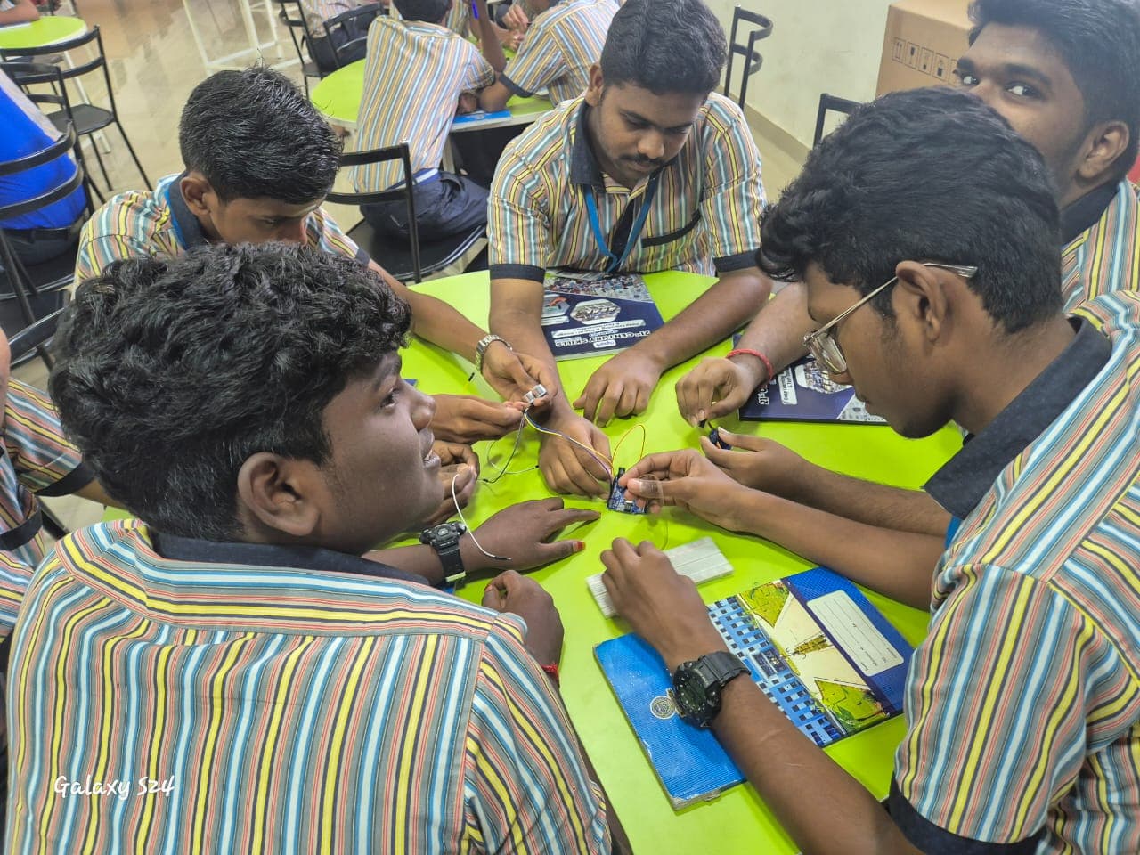
Let’s build.
A low-voltage introductory activity. Never use mains electricity on a breadboard. Start with the “Your first electronic circuit” learning track.
Use only low-voltage DC (5V maximum). Never connect breadboards to AC mains electricity. Always verify resistor value before powering on.
Hardware Bill of Materials (BOM)
Circuit Wiring & Pin-to-Pin Connection Matrix
Regulated +5V Supply Rail330 Ω Resistor (Terminal 1)RedProvides positive DC current feed330 Ω Resistor (Terminal 2)LED Anode (+) Long LegBreadboard TieCurrent limited to safe ~9.1 mA levelLED Cathode (-) Flat RimGround (GND) Bus RailBlackCompletes common ground return pathStep-by-Step Assembly & Verification Guide
- 01
Gather a breadboard, a red LED, a 330 Ω resistor, jumper wires and a regulated 5 V learning supply. Check the LED ratings.
- 02
With power disconnected, connect positive supply through the resistor to the LED anode. Connect the cathode to ground.
- 03
Check the connections and LED orientation. Ask an instructor to review your wiring if you are new to electronics.
- 04
Apply power briefly. If the LED stays dark or any component warms up, disconnect immediately and inspect the circuit.
- 05
Draw your final circuit and record your component values. Share what you learned in the Electronics community.
Reference Firmware Sketch (CPP)
// iSpark Electronics: Bench LED Blinking & Polarity Verification
// Target: ESP32 NodeMCU v2 / Arduino Uno
const int LED_PIN = 2; // GPIO2 on ESP32 NodeMCU (or Pin 13 on Arduino)

void setup() {
  pinMode(LED_PIN, OUTPUT);
  Serial.begin(115200);
  Serial.println("[iSpark] Starting breadboard LED test...");
}

void loop() {
  digitalWrite(LED_PIN, HIGH); // Supply 3.3V/5V logic high (Forward biased)
  Serial.println("LED State: ON (Current flowing through 330 ohm resistor)");
  delay(1000);

  digitalWrite(LED_PIN, LOW);  // Supply 0V ground (Cutoff)
  Serial.println("LED State: OFF");
  delay(1000);
}An introductory learning resource, not an accredited qualification. Check the documentation for your exact hardware and work with appropriate supervision.